
Products
Contact us
ADD: Yanshan Road south, Fengrun District, Tangshan City, Hebei Province
Tel:+86-315-5192200、+86-315-5155128、+86-315-5151706、+86-315-5195522
Fax:+86-315-5192200
Manager Yu:+86-13931535762
Manager Li:+86-13780556733
Manager Guo:+86-15100509068
E-mail:zwzdh@126.com
Zip code:064000
Key words:Orifice flowmeters、Differential pressure flowmeter、Nozzle flowmeter、Wedge Flow meter、Venturi meter、Balanced flowmeter、V-cone flow sensor
ZWZDH-1000 Open Channel Flowmeter
ZWZDH is a high-tech enterprise specializing in R&D, design, manufacturing, marketing of flow meters and industrial automation instruments as well as system engineering integrated services.
Key words:
Classification:
Description
Chapter 1 Overview
Function Description
1. Composition
The instrument consists of a host (controller) and a sensor, which are connected by a 5-core shielded cable.
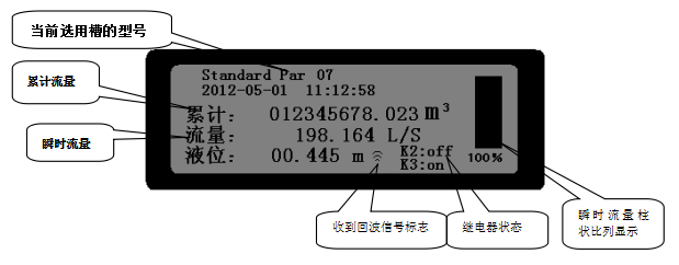
2. Subtitles (display screen content)
Display slot selection information
Display time
Display cumulative traffic
Display instantaneous flow rate
Display liquid level or distance
Display relay status
Display instantaneous flow bar chart
3. Password protection
Protect the internal parameters of the instrument from arbitrary modification.
4. Calibration method
Liquid level calibration method: Set the distance from the bottom of the sensor to the 0 liquid level.
5. Analog output (current output)
Provide a set of 4-20mA outputs (0-20mA to be reserved), 16 bit high-precision D/A, up to 750 ohm load.
The current points of 4mA and 20mA are set by the user according to their needs.
6. Relay output
The controller is output by four relays.
(1) Pulse output relay (K1): When the cumulative value reaches the cumulative value of pulse flow, close once (50ms)
(2) High alarm relay (K2)
(3) Low alarm relay (K3)
(4) Backup relay (K4): designed according to customer requirements when needed.
7. Communication
RS485 interface
8. History
128 historical hourly traffic records
64 historical daily traffic records
32 historical monthly traffic records
4 historical annual traffic records
Chapter 2 Installation and Wiring
After unpacking, count the equipment and check if there are any signs of damage during transportation. If there are any signs of damage, immediately notify the cargo carrier. It is recommended to preserve the packaging and cardboard boxes for instrument storage and reshipment.
1. Controller (transmitter) installation
The controller is wall mounted.
Controller installation requirements:
Clean, dry place
Avoid corrosive liquid gases or require isolation and protection.
Jianyi adds a sunshade in direct sunlight.
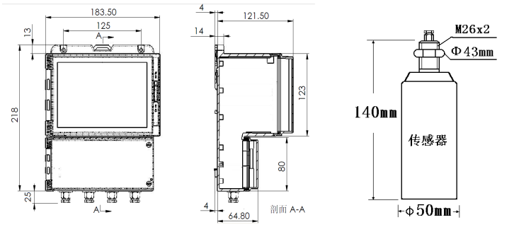
2. Sensor installation
There is a standard 10 meter 5-core cable connection between the sensor and the controller, which is connected according to the corresponding color on the controller.
The transmitter and sensor dimensions are as follows:
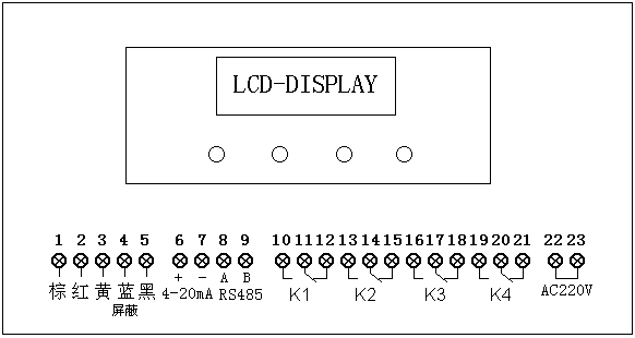
3. Wiring
Chapter 3 Main Interface and Keys
1. Main interface
2. Keys
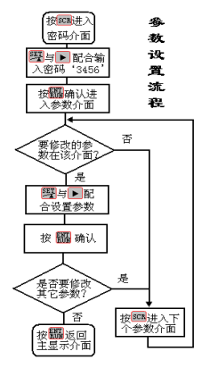
 Change display content: When in the main display interface, press this key to enter the password interface. When in the user parameter interface, press this key to switch to the next parameter interface.
 When you need to enter a password or modify parameters, press this key to enter the setting state. At this time, a flashing cursor will be displayed. Press this key again, and the number of the flashing cursor position will change by adding '1'.
 Move the cursor to the right to the next digit,andCooperate in modifying parameters or entering passwords.
 After modifying the parameters, press this key to confirm (there will be no cursor flashing after confirmation). Press this key again to return to the main display interface
The key operation steps are as follows
Chapter 4 Parameter Interface and Description
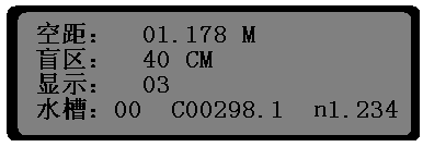
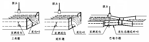
Clearance: refers to the distance from the zero water level to the probe. The definition of zero water level is shown in the following figure. After installation, the correct clearance value should be entered here.
Zero point water level maps of various weir grooves
Blind spot: refers to the distance that cannot be measured from the bottom of the sensor, determined by the characteristics of the probe. Factory set. It is generally 30-50 centimeters.
Display: It can be set to display the distance from the sensor to the liquid level and display the signal sampling reference value.
00 Display distance and signal
01 Display liquid level and signal
02 Display distance and relay status
03 Display liquid level and relay status
Factory settings 03
Sink: sink code settings
00 custom Bashal slots, with C and n values placed according to actual conditions.
01~25 standard Marshall troughs (refer to Appendix 1. Trough Code and Size).
26 V-groove
27 rectangular groove, according to the actual width b value of the weir mouth.
According to this code setting, there will be a corresponding prompt in the position of the "currently selected slot model" on the main interface as follows
code selection
0 User Define Par
1-25 Standard Par XX, where XX represents the number of standard Par grooves.
26 Triangular Weir
27 Rectanglar Weir X.XX m (rectangular weir), where X.XX represents the set width b value of the weir mouth
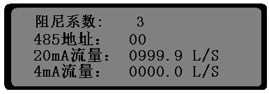
Damping coefficient: The damping coefficient calculated by the instrument, input the numbers' 0-9 ', 0-no damping, 9-maximum damping coefficient.
485 address: Set the communication address. Please refer to Appendix III.
20mA flow rate: corresponding to instantaneous flow rate.
4mA flow rate: corresponding to instantaneous flow rate.
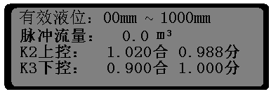
Effective liquid level: The initial effective liquid level and the highest effective liquid level measured by instantaneous flow. When the liquid level is less than the initial effective liquid level value, the instantaneous flow rate is considered 0. When the liquid level is greater than the highest effective liquid level value, the flow rate corresponding to the highest effective liquid level value is regarded as the instantaneous flow rate. The unit is millimeters.
Pulse flow rate: When the cumulative flow rate reaches this value, relay K1 is pulled in once (50 milliseconds).
K2 upper control: Set the upper control relay. The suction point must be greater than or equal to the separation point. The unit is meters.
K3 lower control: lower control relay setting. The suction point must be less than or equal to the separation point. The unit is meters.
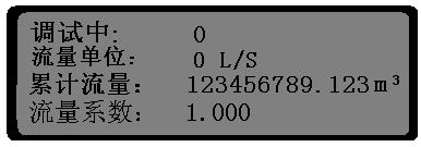
During debugging: If you do not want to generate accumulated traffic during installation and debugging, you can set it to 01. Set to 0 under normal operation.
Flow unit: only set the unit of instantaneous flow; Can be set to '0-4'; 0-L/S liters/second; 1-m3/h m3/h;
2-L/min L/min; 3- m3/min m3/min; 4- m3/S m3/s
Accumulated traffic: The accumulated traffic can be reset
Flow coefficient: Compared to instantaneous flow, input value=actual value ÷ displayed value. Generally, the factory settings are already in place and do not need to be modified.

Time setting
Correction time: Time error correction, with an increase of 1 second for daily time.
Chapter 5 Historical Traffic Query
Press to find hourly traffic, daily traffic, monthly traffic, and annual traffic. In the status of querying traffic records, press to forward search for records that are not displayed.
Hourly traffic: Hourly traffic displays the cumulative traffic per hour, which can store 128 pieces
When in the main interface state, press the key twice to enter the query hourly traffic interface, and then press to cycle through the query.
Daily traffic: Hourly traffic displays the cumulative daily traffic, which can store 64 pieces
After entering the query hourly traffic interface, press the button once again to enter the query daily traffic interface, and then press to cycle through the query.
Monthly traffic: Hourly traffic displays the cumulative monthly traffic, which can store 32 pieces
After entering the daily traffic query interface, press the button once again to enter the monthly traffic query interface, and then press to cycle through the query.
Annual traffic: Hourly traffic displays the cumulative traffic per year, which can store 4 pieces
After entering the monthly traffic query interface, press the button again to enter the annual traffic query interface for viewing.
Chapter 6 Brief Installation and Debugging Steps
1. The instrument is installed and fixed properly, and the cable connection is correct.
2. Measure the distance from the sensor to the 0 liquid level, and set this value as the gap value. (This parameter must be accurate, as it directly affects the accuracy of liquid level measurement.)
3. Select the corresponding 'sink' code according to the actual situation. If it is a Bashar tank, you can also set the code to '00' and then set the C and n values of the Bashar tank. (After setting correctly, it should be able to display the correct liquid level and flow values.)
4. Set current parameters, 485 interface parameters, or relay parameters according to actual needs. (If you don't need it, don't worry about it.)
5. Check if the parameter 'debugging' is' 1 ', and if it is' 1', set it to '0'. When this parameter is set to '0', the cumulative flow rate will only increase, otherwise the cumulative flow rate will remain unchanged.
The flow meters manufactured by our company are widely used in many fields such as metallurgy, chemical, thermoelectric, textile, pharmacy, petroleum, natural gas, paper making, tobacco, food processing, thermodynamics, etc., can be directly connected to DCS systems, suitable for various industrial sites, and can be used as a long-term flow monitoring device. Our first-class product quality and exquisite technical services obtained unanimous praise from the customers.
The company adheres to the business philosophy of "Integrity is the first user", and takes "transforming the most sophisticated measurement technology into the most easy-to-understand and easy-to-operate products" as its responsibility, striving to help customers to provide the best solutions, reduce resource waste, and enhance the effective utilization of resources through accurate measurement. The company pursues the enterprise spirit of "Integrity-based Users first", constantly develops and innovates. It takes technology as the core, regards quality as life, and takes users as God. It strives to create more excellent engineering design, and provides customers with products with higher cost performance ratio and meticulous after-sales service.

Honor
Next
Pre
ZWZDH5800 DTU
Next
Related products


Consultation
Contacts us
ADD: Yanshan Road south, Fengrun District, Tangshan City, Hebei Province
Tel:+86-315-5192200、+86-315-5155128、+86-315-5151706、+86-315-5195522
Fax:+86-315-5192200
Manager Yu:+86-13931535762
Manager Li:+86-13780556733
Manager Guo:+86-15100509068
E-mail:zwzdh@126.com
Zip code:064000
Key words:Orifice flowmeters、Differential pressure flowmeter、Nozzle flowmeter、Wedge Flow meter、Venturi meter、Balanced flowmeter、V-cone flow sensor
 TANGSHAN FENGRUN ZWZDH AUTOEQUIPMENT CO.,LTD | Powered by www.300.cn | SEO | Business license |
  冀公网安备 13020802000189号